
XUV CCD
 The XUV CCD camera is a high-resolution (2k × 2k pixels) camera with 2-channel 12 bit digitization for integration into EUV- and X-Ray telescopes. The camera was originally developed and built by vH&S for a sounding rocket experiment, but it can also be adapted for space-borne instruments.
The XUV CCD camera was successfully flown twice by the Smithsonian Astrophysical Observatory (SAO), Cambridge, MA. Camera development contract (1995-1998) by the Max-Planck-Institut für Sonnensystemforschung, Katlenburg-Lindau.
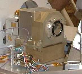
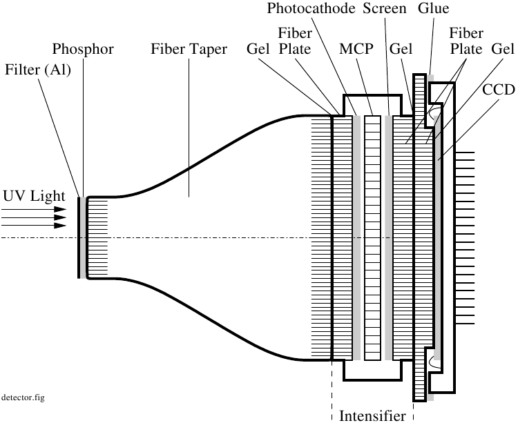 The XUV CCD camera system consists of an optical and an electronic part. The optical part is shown in the Figure. Its task is to preprocess the XUV image at the focal plane for acquisition by a CCD sensor. The XUV light enters through an aluminium XUV filter, which is transparent for wavelengths around 40 nm. A phosphor screen converts the XUV light into visible light. This light enters a fiber taper (ratio 1:3), which adapts the given entrance aperture to the diameter of the image intensifier stage. The intensifier stage uses a single-stage MCP for electron amplification. The photocathode in front of the MCP converts the photons into electrons; it is deposited on the entrance fiber plate of the intensifier. The phosphor screen behind the MCP converts the intensified charge image back into a visible image; it is deposited on the exit fiber plate of the intensifier. The CCD has its own fiber plate, which is coupled to the CCD chip by an optical gel.
The CCD, type TH7899M from Thomson (at this time, now available from Atmel), has 2048 × 2048 pixels of size 14 μm × 14 μm. Different configurations of this chip allow to read out the pixel signals through 1, 2, or 4 pixel output channels. The XUV camera operates the CCD in full frame mode, using 2 output channels in parallel, one at the top and one at the bottom of the image area. The CCD readout timing is generated by a custom FPGA with code developed by vH&S. In case that one CCD output channel would fail, an emergency readout mode has been implemented in the FPGA, where the full frame is read out through the remaining channel.
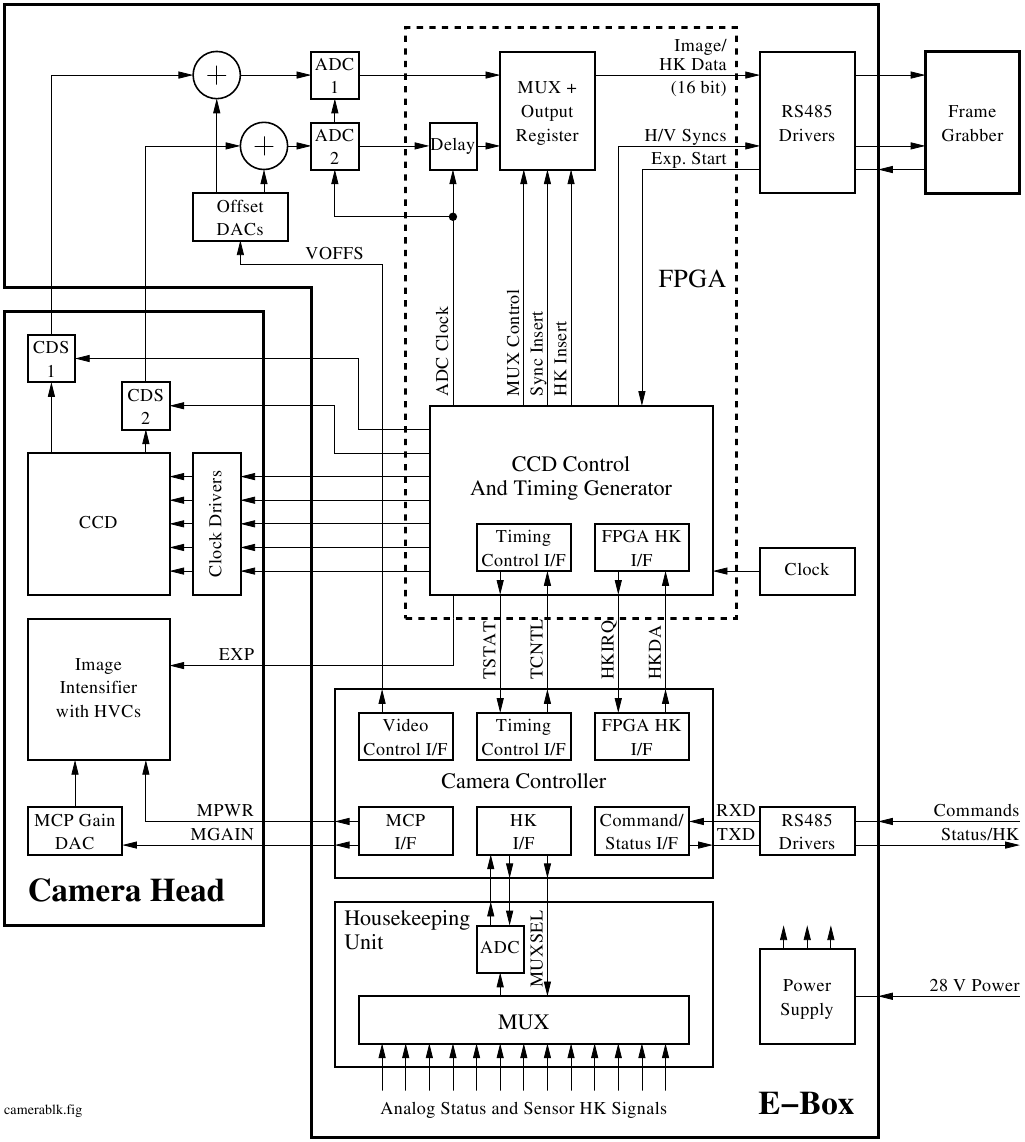 The XUV CCD camera system consists of two subunits: 1. the camera head (focal plane electronics) with intensifier, CCD, CCD cooling and temperature regulation system, clock drivers, and video front-end electronics, and 2. the electronics box containing a custom-designed 2-channel correlated double sampling (CDS) system, two video ADCs, central control FPGA, interfaces, and power supply. The block diagram is shown in the Figure.
The FPGA code designed by vH&S does the overall camera system control, generates the CCD readout sequencing, provides emergency mode capability, generates the CDS and ADC timing, does the data formatting for a synchronous serial video data interface, and acquires all housekeeping data. The FPGA has a control interface for camera configuration.
Company vH&S developed and manufactured the entire camera electronics, software, and electronics box mechanics. Company ProxiVision GmbH (Proxitronic Detector Systems back then) provided the taper with entrance filter and phosphor, image intensifier, and coupling of a custom fabricated fiber plate to the CCD. The MPS built the focal plane optomechanics and did the camera end integration and testing.
Simulation of fiber-optical system, MCP intensifier, and CCD
The optical path consists of a sequence of fiber structures (taper, fiber plates), image intensifier, CCD, which share several optical interfaces. All these structures perform some spatial sampling: A photon may fall into one fiber within a fiber plate, or into the next fiber. Then on the exit side of the fiber plate the location of the photon is randomized over the area of the fiber. A stack of several fiber structures, as with the described CCD camera, therefore will spread up a light beam not unlike a bean machine (Galtonsches Brett). Similarly the MCP does spatial sampling as the photons are converted into electron clouds, which are intensified while travelling the individual tubes from which the MCP is made up.
Also the image intensifier has some transfer characteristics and blurring effects given by its general working principle.
To get an rough impression about the optical performance of such a rather complex fiber/imager/CCD stack, vH&S has developed a simple software toolbox, which does a Monte-Carlo simulation of such a stack. Basically a large number (e. g., one million) of photons is generated in form of some pattern on the entrance aperture. In the simulation these photons are then sampled by the fibers of the taper, which are arranged in a hexagonal (honeycomb) structure. The photons further travel though the fiber and intensifier structures until they are finally collected by the CCD, and converted into an output image.
In the simulation each photon is represented by its (x, y) location. For each optical structure a function has been written (e. g., honeycomb sampling for fiber plates), which samples the (x, y) coordinates in the image plane for each photon and maps it to a new (x, y) coordinate on the output side. The photon density is linearly related to the intensity. To get an image, the CCD builds up a pixel-by-pixel histogram from the incoming photons.
The simulation is not calibrated, the models are far from perfect and use only the most prominent effects, so do not expect any quantitative result. The toolbox was originally written as a set of AWK scripts managed by a Makefile. We have converted these scripts into a Lua program, which allows easier control of the parameters and faster simulations. Input and output images are in the portable graymap (PGM) format.
We provide our tiny simulation toolbox, which is still work in progress, as free software, open source with LGPL license, in the hope that it may be helpful. The simulation software can be downloaded below. Feedback is greatly welcomed, particularly regarding realistic MCP and intensifier modelling.
Downloads
XUV Simulation Toolbox: TGZ-Archive (3.5MB)