
VATSY
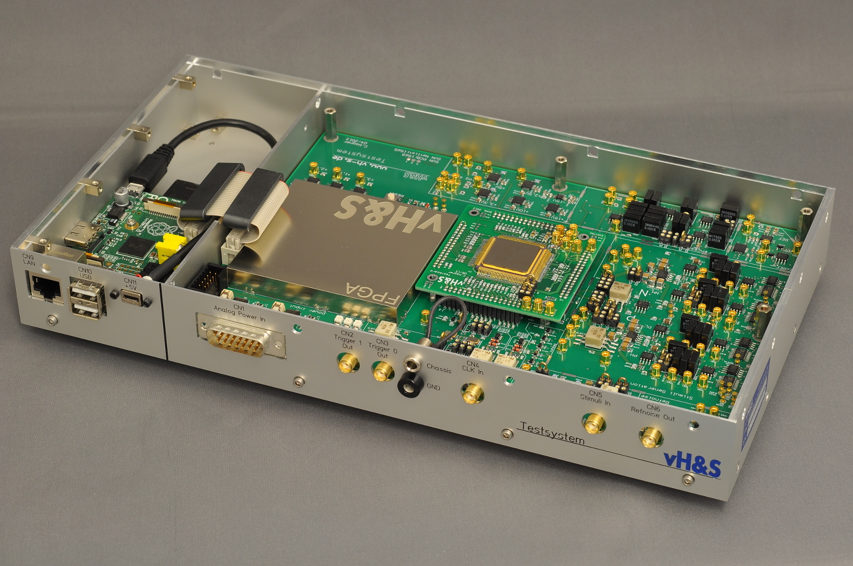 The Video ADC Test System (VATSY) is a product by vH&S, which allows to measure the key performance parameters of video analog/digital converters (ADC) with very high precision. The system has been optimized particularly for the new rad-hard video ADCs of type VASP (VASP-PROTO, VASP1, VASP2) from Thales-Alenia France, which are used in space instrumentation (earth observation etc.).
The measured performance parameters are:
- Integral non-linearity (INL)
- Differential non-linearity (DNL)
- Noise spectrum
- Input common mode range
- Input common mode rejection
- Large step impulse response and settling
- Aperture jitter
- Thermal drift
The test system VATSY is designed to provide reliable data for ADCs with a resolution of up to 16 bit and a sampling rate of up to 4 MHz. The step response measurement has been especially designed for the performance needs of ADCs for precision imaging by CCD, APS, or infrared sensor Read-Out-ICs (ROIC). VATSY adapts to different ADC types through adapter boards, which are custom-designed after the pinout and signal requirements of the individual ADCs. The ADC data output lines may be serial or parallel, with CMOS and LVDS level standards. A transparent I2C bus interface allows to set up the ADC configuration, if needed.
The test system provides various programmable stimuli, all in both single and differential modes, and with programmable common mode voltages:
- DC values through four high-precision 20 bit DACs
- Programmable high-speed large-scale steps with 20 bit plateau resolution, very low output impedance, and fast-settling (< 10 ns to sub-LSB)
- Stable high-speed sawtooth signal for aperture jitter measurement
- External stimuli input through SMA connectors, converted to differential
All voltages are directly derived from a precision DC reference source with low drift. Analog circuitry for bias generation and handling of analog video signals uses precision high-speed op-amps and low-drift metal foil resistors (TK < 2 ppm/K). A low-jitter quartz oscillator (48.000 MHz) provides the master clock for the system, from which the ADC sampling clock and all other clock signals are derived. All potentially jitter sensitive lines are re-sampled directly to this master clock. For even better jitter performance an external precision oscillator may be connected through an SMA connector.
The test system can be configured very flexibly for various test modes. The configuration of the data paths and the stimulus selection are done manually by low-ohmic, gold-plated metallic jumpers, rather than by CMOS switches. By this the critical signal lines keep very low impedances for optimum test signal integrity. The manual configuration is optimized for testing of individual ADC specimens with high precision, but this may preclude the use of the system for testing large ADC batches.
The overall real time operation of the test system is controlled by a re-programmable FPGA, which manages all real-time tasks, like stimulus generation, ADC data acquisition, and video data buffering in an on-board RAM. The FPGA code may be adapted to the requirements of ADC test specimens. The test system is operated by an embedded ARM controller board with Linux operating system, where the test sequence and signal analysis are controlled through a scripting language.
The VATSY can be used as self-standing test system by connecting monitor, keyboard, and mouse. It may as well be operated remotely through an Ethernet connection, and all test data are available transparently.
Contact:
- Dr.-Ing. Hartmut Henkel (henkel@vh-s.de)